
A hollow rotary platform combines a rotating mounting surface with a central passage for wiring, piping, tooling, or optical access. It can simplify the construction of indexing stations, inspection fixtures, assembly machines, and handling equipment. Selecting the right unit requires more than matching table diameter to workpiece size.
A hollow rotary platform must support the actual motion profile, fixture inertia, external loads, and positioning tolerance. The central opening describes its geometry, not necessarily its drive architecture. Geared motor-driven units and direct drive arrangements can both have hollow centers.
Define the process requirements before comparing product specifications. A hollow rotary platform that performs well in a light inspection station may be unsuitable for an offset assembly fixture, even when both applications carry the same total mass.
Begin with the required rotation angle, direction, positioning time, dwell, and cycles per hour. State whether motion involves repeated indexing, oscillation, variable positioning, or continuous rotation. A hollow rotary platform should be selected against this complete operating sequence.
Separate movement time from settling time and process time. A hollow rotary platform that reaches its target quickly may still need additional time for vibration to decay before a camera captures an image or a tool engages the workpiece.
Record normal and exceptional conditions, including empty fixtures, maximum payloads, reversals, and controlled stopping. Include expected future product changes so the hollow rotary platform has a defined operating envelope rather than an unspecified reserve for every possible modification.
Payload mass alone cannot predict acceleration demand. A hollow rotary platform carrying components near the axis experiences less load inertia than one carrying identical components around a large perimeter. Fixture geometry therefore matters as much as weight.
For a uniform annular plate about its central axis, use:
J = 0.5 × m × (r_outer² + r_inner²)
For a small component concentrated at radius r, use J = m × r². Sum the fixture, adapters, workpieces, and other rotating attachments supported by the hollow rotary platform.
Use consistent units and reference every inertia to the output axis. A hollow rotary platform selection based on motor-shaft inertia requires the appropriate conversion; do not compare input-referenced and output-referenced figures directly.
Acceleration torque follows T = J × α, where J is rotational inertia and α is angular acceleration. Add friction, cable resistance, and process torque using their actual directions. A hollow rotary platform may encounter different torque requirements during acceleration, travel, and deceleration.
Calculate the maximum demand from the intended motion profile. For a hollow rotary platform using a jerk-limited profile, peak acceleration can exceed a simple average estimate. Use the actual programmed trajectory or a suitable sizing calculation.
Compare required torque with continuous, cyclic, acceleration, and peak limits as defined for the unit. A hollow rotary platform holding-torque specification does not automatically establish its allowable running torque at speed or its capacity for repeated starts.
Consider a 2 kg annular fixture with a 0.15 m outer radius and a 0.05 m inner radius. Four 0.2 kg workpieces sit at a 0.12 m radius. The hollow rotary platform must move 90 degrees in 0.50 seconds using a symmetric triangular velocity profile.
The fixture inertia is 0.025 kg·m², and the workpieces contribute 0.01152 kg·m². Total external load inertia is therefore 0.03652 kg·m², excluding any additional adapters.
For this rest-to-rest profile, α = 4θ / t². With θ equal to π/2 radians, acceleration is approximately 25.13 rad/s² and peak speed is 60 rpm. The hollow rotary platform needs approximately 0.918 Nm to accelerate this external inertia.
If resisting torque is assumed to be 0.4 Nm, the accelerating output demand is approximately 1.318 Nm. This example does not establish a final hollow rotary platform rating: internal inertia, transmission losses, motor capability, cable forces, bearing loads, settling, and duty still require verification.
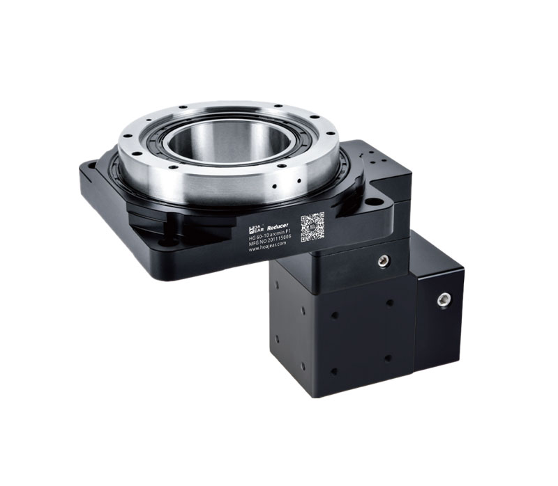
Output torque and bearing capacity are separate requirements. A hollow rotary platform must withstand axial force, radial force, and overturning moment in the actual installation. A torque calculation alone cannot confirm structural suitability.
For an offset force, moment magnitude follows M = F × e, where e is the perpendicular distance from the relevant support reference. A hollow rotary platform carrying a tall fixture can experience substantial overturning moment from a relatively modest horizontal process force.
Check combinations of loads rather than assuming every individual maximum is simultaneously available. Use the specified bearing-life and load-combination method. A hollow rotary platform with adequate static capacity may still have unacceptable deflection or insufficient bearing life under repeated dynamic loading.
Distinguish positioning accuracy, repeatability, resolution, and lost motion. Accuracy concerns closeness to the commanded angle; repeatability concerns consistency under defined conditions. A hollow rotary platform can have good repeatability without equally good absolute positioning accuracy.
Specify performance at the working point. For small angles, linear displacement is approximately δ = r × θ, with θ in radians. An illustrative 0.02-degree angular error at a 150 mm radius corresponds to approximately 0.052 mm of tangential displacement.
A hollow rotary platform used for vision inspection may also require limits on radial runout, axial error motion, and tilt. Evaluate the hollow rotary platform with representative payloads, both approach directions, and warm operating conditions rather than relying on encoder resolution alone.
For a geared hollow rotary platform, backlash and elastic deformation can affect reversal and disturbance response. Low backlash does not imply infinite stiffness, and mechanical preload does not eliminate every source of lost motion.
Check whether feedback measures motor position or actual output position. A hollow rotary platform with motor-side feedback may not directly detect every displacement in the downstream transmission. Output feedback can improve observability but does not remove mechanical deflection from the structure.
Include fixture plates, couplings, fasteners, and the machine frame in the stiffness assessment. A hollow rotary platform with precise internal components cannot compensate for a flexible mounting plate or an unstable workholding arrangement at the process location.
Choose the usable opening around the complete routed assembly rather than the bare cable diameter. A hollow rotary platform may need space for connectors, hose bend radii, strain relief, protective sleeves, and maintenance access.
Check the opening after installation of adapters, transfer devices, and guarding. A hollow rotary platform bore that appears sufficient in a catalog can become obstructed by a mounting plate or connector arrangement in the finished machine.
For continuous rotation, cables and hoses usually need suitable rotary transfer arrangements. The hollow rotary platform opening does not prevent twisting by itself. Verify slip-ring or rotary-union compatibility with speed, electrical requirements, pressure, media, contamination limits, and the intended service environment.
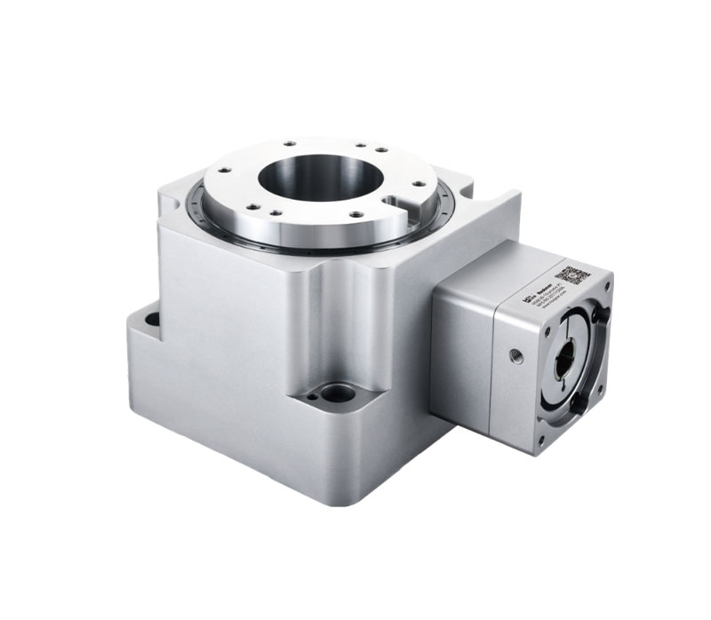
A hollow rotary platform may use a stepper motor, closed-loop stepper system, servo motor, or direct drive motor. Choose the complete arrangement according to speed, torque, feedback, integration, and required motion behavior.
For a geared hollow rotary platform, reduction changes both motor speed and reflected load inertia. In an ideal model, reflected inertia equals load inertia divided by ratio squared. Include transmission and coupling inertia when evaluating motor matching.
Confirm driver compatibility, power supply, communication interface, homing method, and alarm handling. A hollow rotary platform should integrate with the machine controller without requiring uncertain assumptions about encoder signals, command scaling, or positioning behavior following a fault or power interruption.
State whether the rotating axis is vertical, horizontal, or inclined. A hollow rotary platform may have different load restrictions, lubrication requirements, or motor-mounting options for different orientations. Confirm the actual arrangement from the configuration drawing.
With a horizontal rotation axis, an offset center of mass can create angle-dependent gravity torque. With a vertical axis, an eccentric payload can create overturning moment. A hollow rotary platform must be checked against the appropriate forces rather than only total fixture weight.
Verify housing support, fastener access, motor clearance, and component removal paths. A hollow rotary platform that fits inside the machine may still be difficult to service if the motor or cable connector is trapped behind the frame.
Operating hours, starts per hour, reversals, and dwell all affect selection. A hollow rotary platform that handles occasional adjustment may not suit continuous indexing at the same peak torque. Confirm thermal behavior over the complete production sequence.
Specify ambient temperature, dust, moisture, cleaning chemicals, and any cleanliness or vacuum requirements. A hollow rotary platform should have documented suitability for the actual exposure; an enclosure rating does not establish compatibility with every cleaning method or chemical.
Check lubricant requirements and maintenance access. A hollow rotary platform described as sealed or lubricated for life still has defined operating assumptions. Monitor temperature, vibration, leakage, and positioning trends rather than interpreting that description as unlimited service without inspection.
Define normal stopping, emergency stopping, and power-off holding separately. A hollow rotary platform may need motor torque to maintain position, and a geared arrangement should not be assumed to prevent backdriving under every condition.
For gravity-loaded mechanisms, specify the required brake or restraint. Confirm whether a brake is intended only for stationary holding or is rated for dynamic stops. A hollow rotary platform assembly may also need appropriate drive braking capacity to absorb or return deceleration energy.
Document behavior after an alarm or power restoration, including position verification and homing. A hollow rotary platform should restart according to the machine's intended sequence rather than move unexpectedly because stored commands or references were not handled correctly.
| Selection item | Information to verify |
|---|---|
| Motion | Rotation angle, direction, movement time, settling, and dwell |
| Inertia | Complete rotating assembly referred to the output axis |
| Torque | Acceleration, friction, process forces, reversal, and stopping |
| Bearings | Axial force, radial force, moment, deflection, and required life |
| Positioning | Accuracy, repeatability, lost motion, runout, and tilt |
| Center passage | Usable bore, connectors, bend radii, and rotary transfer devices |
| Integration | Motor, driver, feedback, controller, power supply, and alarms |
| Installation | Orientation, mounting rigidity, clearance, and service access |
| Operating conditions | Duty cycle, temperature, exposure, lubrication, and holding |
Install the hollow rotary platform on a clean, rigid surface using the specified fasteners and tightening procedure. Confirm fixture clearance and cable behavior throughout the intended motion range before applying production loads.
Test representative payloads and approach directions, then measure settling, temperature rise, positioning consistency, and process results. A brief unloaded demonstration cannot establish whether a hollow rotary platform will meet the actual cycle time with changing workpieces.
Record acceptance results and configuration details for maintenance. If performance changes, check workholding, cable resistance, mounting connections, and control settings alongside internal condition. A hollow rotary platform selection is complete when the installed machine meets its defined motion and process requirements.
Confirm exactly what the quoted assembly includes. A hollow rotary platform may be supplied as a mechanical unit, a motorized actuator, or a package with a driver and cables. Identify required adapters, brake options, software access, documentation, and commissioning support. Comparing identical supply scopes prevents an apparently lower equipment price from concealing additional integration work.
No. Inertia, acceleration, process torque, bearing moments, and accuracy also matter. Loads with the same mass can impose very different demands.
No. Select the opening for routing and tooling requirements, then separately verify torque, bearings, speed, stiffness, and the available installation space.
Only with a suitable routing or transfer arrangement. Ordinary fixed cables can twist, so continuous rotation may require slip rings or rotary unions.
Provide fixture drawings, load distribution, motion profiles, process forces, positioning tolerances, bore requirements, environment, installation orientation, and controller details. Include stopping and holding requirements so the proposed assembly can be checked as a complete system.
QR Code

ada apa
Surat

Situs web ini menggunakan cookie untuk memastikan Anda mendapatkan pengalaman terbaik di situs web kami.


 EN
 Español
 Pусский
 Tiếng Việt


 ada apa
 Telepon
 Surat
 pesan
Komentar
(0)